An infill project with a modern twist

UKworkshop.co.uk

Help Support UKworkshop.co.uk:

This site may earn a commission from merchant affiliate links, including eBay, Amazon, and others.

Pekka Huhta

Established Member
Joined
19 Jul 2006
Messages
412
Reaction score
0
Location
Finland
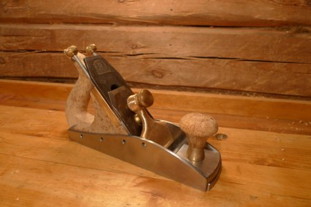
I started building an infill plane in 2009. It all started when I had an idea for a new adjusting mechanism and I wanted to build a plane around it. Another major idea for the plane came from UKWorkshop when I saw the infill smoother Aled was building. It had a screw-on construction, and as I have been building different planes with adjustable mouths, I figured out that it would be dead simple to build an infill plane with an adjustable mouth just by bolting the "sole" in front of the mouth 10 mm higher and inserting the sliding mouthpiece just below it. I almost felt stupid for not figuring it out earlier, it was so obvious

Although I love old tools, I sometimes dislike the... ornaments, in lack of a better word. Look at the side of an old Norris or Spiers. If you look at the shapes and not at the tool, you just see a quite clumsy wave shape in the side. The tool itself is beautiful, but the details are not. It's not a flowing line, not particularly ergonomic, there is nothing to explain why it is what it is. So I wanted the lines of my plane to be flowing, smooth, and that created the very simple side line of the plane. A tad of Finnish Design, if you like :) As I could not decide what width I wanted, I decided to build two different planes, for 2¼" and 2½" irons.

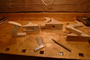
I made a set of drawings, but I wanted to see how the plane felt to my hand, so I built a quick mock-up from plywood and workshop offcuts.
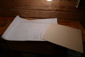
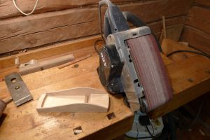
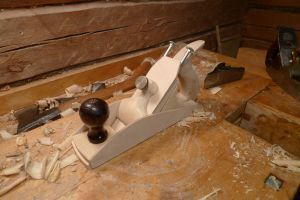

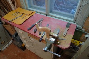
I have a friend who got the parts laser cut in his company. I was able to machine the sides of the soles + all the fixing holes at my previous job. After that I just started putting things together. The holes were chamferred and the whole frame bolted together. I also noticed that you should not put too deep chamfers there: first set of sides was ruined by too deep chamfers, as you could not file the slots in screwheads off. Also, the screws had to be with a straight slot, as the phillips slots were so deep that you had to file away the whole head before the slot disappeared.

I used acid to dissolve the zinc coating on screws as I figured out that the zinc could show as a narrow ring around the screw head. And while I was at it, I also hammered the screw heads flat, to make sure that the screws fit perfectly in the hand-drilled chamfers.
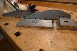
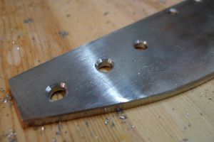
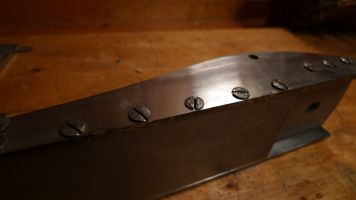
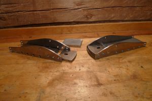
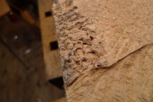
Next thing was the handles. I had a lump of Karelian birch and I sawed the infills and handles out of it. The wood is beautiful, but if you look at the picture where I have split the wood you can see that there is absolutely no grain orientation (other than "every way"). You need pretty sharp tools with that stuff.
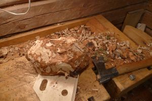
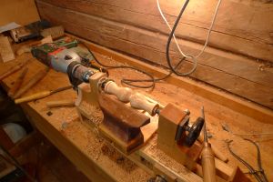
The knobs were turned with my small lathe. It may be pretty, but it isn't particularly practical. I ended up turning both of the knobs at the same time to save time. I drilled the hole for the screw first and centered the blank around that hole, as i knew thet I could not drill the hole to the center afterwards. I only drilled the bigger hole for the fixing part after sawing the knobs off.
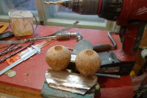
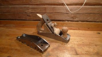


...and that was it from 2009. There were multiple problems: I had designed the sides slightly wrong so that the lever cap hole was about 3-4 mm misplaced, which made the levercap look like shait as it was sticking almost vertcally up if I tightened the screw. The knobs were far too high and both looked and felt awful. The Karelian birch was not totally dry and the infills shrunk so that there was a 0,5 mm gap all around the infill. I also wanted to make my own castings and I needed a forge. So I built a forge, which took about a year to finish and then I just let the whole project sit on the shelf to wait for inspiration.

And on the contrary what you would expect: lo and behold, the inspiration came a few months ago (hammer) I had just finished my oak bookcase and wanted to do something else before starting a new renovation project in the house.

I will try to update as I go. I have now cast the lever caps (will have to edit the pics before posting) and turned a new knob. And built the new adjuster mechanism. Now it's time to finish the infill for the first plane and start putting things together...

Pekka
 
Lovely stuff as usual my friend!!

You mention the Norris and Spiers and the wave design...I think that you will find as you build these things further that the design comes from tried and tested elements which all interlink to make functionality work.

You mentioned for instance the lever cap mounting. The top of the wave in traditional infills is to give enough metal above it to prevent cracks in cast steel and distortion in dovetailed models hence the peak of the wave.

The flow of the wave behind it generally follows closely the end of the bed as it rises up...the undulation in between is just a matter of mathematical joining the dots.

The downward sweep at each end then reflects the need to reach close to the bottom at the rear to get the right place for the handle and rising at the front to hold the bun.

So what may look like a bit of Art Nouveau is in fact structure and maths....with a few 19th Century curves and bevels thrown in.

I like the take on the sliding mouth...which is done a different way in modern BU fore and jointer planes and of course..in the 60 1/2 and 90 1/2 block planes of Bailey design. I'm interested in your adaptation and how you keep registration and prevent movement side to side. Do you have any drawings?

I've seen your work with Karelian birch before and it is indeed a stunning wood and ideal for infills because of the grain...should be super tough and won't break at key points. That's why I like using burrs and boxwood for these elements...they are much stronger than the cheaper mahogany stained or even rosewood traditions.

I will be watching this post with fascinations...and if you can throw in a bit about your lever cap moulding work it would be wonderful!

Excellent!

=D> =D> =D>

Jim
 
Very, very good. I like the thickness of the sole. Much less difficult without cutting dovetails.
The "wave" only needs to peak at the high point of the pivot; how it gets there and back again is open to limitless interpretation. =D>
 
I think I made too big a number about the "dislike" of the old designs. I really love them, but when I build a tool I am not that good at drawing those ornaments to my design. Richard got it spot on: the pivot point has to be high, ends should be pretty low, there should be some room for the front hand, but everything else is just visual.

What I meant was that there are lots of other features in the shape in addition to the functional.

http://www.thebestthings.com/oldtools/g ... 120963.jpg
http://www.thebestthings.com/oldtools/g ... 81233a.jpg
http://www.thebestthings.com/oldtools/g ... 12044a.jpg
http://www.thebestthings.com/oldtools/g ... 20167a.jpg
http://www.toolbazaar.co.uk/gallery/tools/9.jpg

Those are in no way ugly. Especially on the panel planes the lines have much to add to the beauty of the tool. Just about the only really ugly hand plane I know is the infamous Plane-o-ayr, which looks like a snake who has eaten an elephant :)

image002.jpg


I think the backsaw I made a good while ago is a good example of the visual lines I tend to build myself. I built my own saw and Klaus&Pedder built another one for me. I really love the Two Lawyer's saw and tend to use it more often than the saw I built myself. The two lawyer's saw represents the old, beautiful and ornamental traditional handle. Mine has the same ergonomical features - long horns in the top and bottom to support the hand, similar hump in the back of the handle to fit your palm, but between these functional features there are just straight lines. I somehow wanted the plane to be built with the same idea, smooth and slick.

kakssahaa.jpg


Pekka
 

Attachments

  • kakssahaa.jpg
    kakssahaa.jpg
    75.3 KB
It has been a long project, but some things sometimes get done. I should be able to get the plane(s) ready soon, so I'm trying to catch up with the story.

Casting the lever caps was not that difficult after getting the furnace built. It's just a coal fired furnace built from a gas bottle. Here is a pic showing what it looks like under the insulation.
Ahjo.jpg


I made the pattern for the lever caps from wood and then just bought a small bucket of casting sand to make the molds.
P1020336.jpg


To separate the layers of casting sand I just used potato starch between the top and bottom half.
P1020340.jpg


And after some casting...
valu.jpg


...Voilá:
infill_valu.jpg


Hopefully the next update is sooner than in two years... :roll:

Pekka
 

Attachments

  • Ahjo.jpg
    Ahjo.jpg
    123.8 KB
  • P1020336.jpg
    P1020336.jpg
    41.9 KB
  • P1020340.jpg
    P1020340.jpg
    43.7 KB
  • valu.jpg
    valu.jpg
    62.8 KB
  • infill_valu.jpg
    infill_valu.jpg
    63.6 KB
I am liking that furnace a lot. You have seriously tempted me - my father has an old gas bottle to get rid of too ...

What did you use for the crucuble ? Can you buy them ?

Excellent stuff !
 
Sheffield Tony":39cpblj9 said:
I am liking that furnace a lot. You have seriously tempted me - my father has an old gas bottle to get rid of too ...

What did you use for the crucuble ? Can you buy them ?

Excellent stuff !

Try http://www.johnwinter.co.uk/model-engin ... ngineering for equipment and supplies, and for reading matter the Workshop Practice Series books 'Foundrywork for the Amateur' and 'The Backyard Foundry' both by B Terry Aspin.
 
The story is only as good as the cast!

:roll: :oops:

Ok...that's a bad one even for me!! :mrgreen:

But that is seriously creative and an inspiration to others who wish to make their own castings.

I was tempted but frankly all this high temperature stuff scares the be-geeesus out of me...I can only just cope with hardening and even then with a kiln!

But the results seem to prove that you can add another few strings to your bow my friend...pattern maker and foundry engineer!

Superb stuff!

Oh...and I'm glad you liked the spokeshave...I thought that might be right up your street!! :mrgreen:

Jim
 
I got a hold of various gas tanks, mostly dive tanks. The furnace is made from a He/O2 tank. The crucible is the bottom half of a smaller tank. Can't really recommend as it really starts oxidising and flaking only after a couple of casts. The bottom of a third, smaller tank is cut to the bottom of the furnace to distribute the air more evenly. I have since made the coutouts much wider and I still feel that there should be more air coming out.

A ceramic crucible is in order, I am hoping to make a few more lever caps and possibly a small block plane when I next heat it up. The crucible is perfect to handle with the "fork" I have for it, it really is good for pouring. But a steel crucible just can't take the heat, so it's quite useless for anything than trying out what casting is like.

Pekka
 

Attachments

  • Pohjakupu.jpg
    Pohjakupu.jpg
    70.7 KB
jimi43":33dcm2v2 said:
The story is only as good as the cast!

:roll: :oops:

Ok...that's a bad one even for me!! :mrgreen:

Ha! I was afraid that someone would ask :wink:

We seemed to have posted at the same time so I did not notice this post before I sent my previous one. Before you get scalded for bad puns about casting let me thank you about the spokeshave; it really was spot on what I have dreamt of. One day I will make my own, but before that it is important to have a good one to compare to, to learn how a well-made tool behaves. It is a gem.

But to the casting: I have a pictorial about the second try. I tried to cast some brass with my friends earlier with no great success - the furnace just did not get hot enough before I insulated it and improved the air flow. They came over half a year later and they were thrilled to hear I had improved the furnace since and insisted that of course we should try it out right away. I only had the 1:1 pattern (in fact a mockup used for the plane) without any allowances for the shrinkage of the metal and I made the molds while my friend coaled up the furnace.

I am uploading the pictures to my website and resizing them, but as it seems to take a few hours, here is the climax:

here_it_goes.jpg


It's easy after you have done it a few times. Biggest risk is moisture: if you have the tiniest drop of water anywhere near the molten metal, you will get all of it to your face.

We once did cast 900 kg of tyre weights (lead) as to ingots for the ballast of a traditional fishing boat. One time a friend of mine tried to add fresh weights to the hot crucible and the result was that we got a rain of liquid lead when the moisture trapped in the lead weights evaporated in an explosion as the water hit the 300 degree pool of molten lead. It was not fun, but fortunately nobody was badly burnt. You can imagine how aggressive it can be if there is the tiniest bit of moisture in contact with 1400-deg brass.

I had a few ingot molds just welded together from angle irons and you really do have to scorch them with a gas torch to get the moisture out before you pur the leftover brass into them.

Pekka
 

Attachments

  • here_it_goes.jpg
    here_it_goes.jpg
    40.2 KB
Pekka Huhta":6cq9d9ri said:
The casting process can now be (hopefully) seen at

http://images.sihistin.fi/main.php/v/valu/

Please be patient, it's on a slow server and it may have to still resize the images when someone opens them for the first time. Please let me know if it does not work properly.

Pekka

Ha! I'm glad you like it. Dixon is a fine maker and the brass work on that example was something that attracted me to it. I admit to doing some drawings myself and a rough blank of the handle so that I could copy it myself before I sent it over! I am making one out of cocobolo but more on that for another day....no time to finish it at the moment.

Your WIP photos are particularly useful. It's the bit between IMG3432 and 3436 that makes my hair stand on end. Molten metal is something I would rather be very far away from! I truly admire the old boys in those foundries where they pour huge crucibles of the stuff into moulds and move along...frightening!

It looks as if you have no fear of the volcanic nature of this craft!!!

I suspect you will be making many brass parts now you have the skill!

Bravo!

=D> =D>

Jimi
 
In fact they are a tiny little bit asymmetrical, but not that way as the image suggests. Other "shoulder" of the lever cap is a tiny bit higher than the other, but in the pic it looks like they would be somehow crooked.

Next pictures aren't about cleaning up the castings, as there are some spoilers in the pictures. I did not like the Stanley-type knob at all, it was all too plain. Another reason for disliking it was that I knew that the old knobs tended to crack near the base of the knob, and that was why Stanley added the cast ring around the knob.

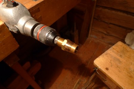
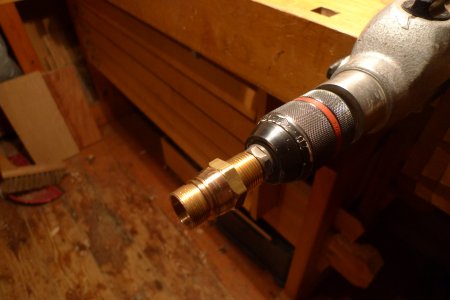
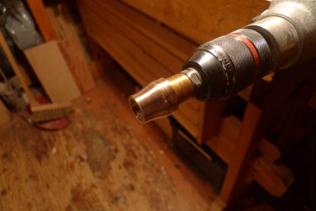
To avoid splitting I decided to make the lower part of the knob from brass. I do not have a metalworking lathe, so the best way to turn the brass piece was to just chuck a part of a brass cable gland in a drill and file away.

P1020269_450.jpg
P1020270_450.jpg

P1020271_450.jpg
P1020274_450.jpg


The shape of the knob is very comfortable, it gives a wider rest to the palm than just a round Stanley knob. I am pretty happy with the shape, although the whole knob could have been a tiny bit bigger in every respect.

Pekka
 
Wow Pekka - looks great.

And your lathe(s) are something to behold. :) I have to slum it with a Myford. Very good use of the brass fitting.

You know you're going to have to tell us about the adjuster at some point ... looks surgical.

=D>
 
The adjuster is simple. I have never learnt to use the Norris type adjuster so that it would feel natural, it seems that I always mess the sideways adjustment when adjusting the depth or then have to stress myself trying not to.

I had two preconditions when designing the adjuster: no special threads or special machining operations. And somehow the idea of having two visually identical adjusters both sides of the tote felt like a nice touch. After that it was just a matter of figuring out the right configuration.

Depth adjuster has an about 1:3 lever, so with a M6 thread the adjustment is roughly 0,3 mm per one turn of the screw. Sideways there is a lighter ratio, as there is a lot less force required to move the iron sideways.

Depth adjuster fits to a square hole in the cap iron, and side adjuster fits into a groove filed to the plane iron itself.

The adjuster box is dovetailed together and screwed to the infill. I am quite happy with the operation: there is only a minimal amount of backlash in the adjustments and the adjustment feels accurate enough for my use. I will still have to tweak things a bit, moving the whole adjuster box about 2 mm towards the mouth as I had planned machining the sole flat and I had taken some allowance for a thinner sole. I ended up just lapping the sole flat at home and the adjuster is slightly too far back.

I think it is quite simple and easily manufactured. And it's nice to think that now there is again one new way to adjust the plane iron, I bet that one hasn't been tried earlier.

Pekka
 

Attachments

  • P1020790_800.jpg
    P1020790_800.jpg
    69.4 KB
Pekka Huhta":2fxm8kr4 said:
In fact they are a tiny little bit asymmetrical, but not that way as the image suggests. Other "shoulder" of the lever cap is a tiny bit higher than the other, but in the pic it looks like they would be somehow crooked.

Next pictures aren't about cleaning up the castings, as there are some spoilers in the pictures. I did not like the Stanley-type knob at all, it was all too plain. Another reason for disliking it was that I knew that the old knobs tended to crack near the base of the knob, and that was why Stanley added the cast ring around the knob.

To avoid splitting I decided to make the lower part of the knob from brass. I do not have a metalworking lathe, so the best way to turn the brass piece was to just chuck a part of a brass cable gland in a drill and file away.

P1020269_450.jpg
P1020270_450.jpg

P1020271_450.jpg
P1020274_450.jpg


The shape of the knob is very comfortable, it gives a wider rest to the palm than just a round Stanley knob. I am pretty happy with the shape, although the whole knob could have been a tiny bit bigger in every respect.

Pekka

Oh man!!! You've just given me the biggest BING! *inspiration hits* with this particular post - chucking up that brass part in the drill to shape it, threaded onto another fitting - so ridiculously obvious, yet it still eluded me (I actually yelped "DUDE.. OF COURSE!!" at the screen with vociferous gesticulations) for something I've been mulling over a while.

How simple was it to shape? how long did it take and was there anything you encountered a person doing this should look out for?

It's a great WIP and your furnace looks like something most handy people could knock up - though the warnings of the pouring and casting sounded ominous, lead rain.... (although that's how shotgun pellets are made btw) glad no-one got hurt.

Loving the look of the plane and you are right, the lines look so much better, I note the front handle shape too, I might make the same modification at some point in the (probably distant) future.

I also really like that adjuster, but do you think it would be possible to make one that works the same way as a spokeshave? I had an issue with one of my planes where I had sharpened it to an angle instead of 90deg to the side of the blade and even putting it diagonally on the frog and full adjust it wasn't quite straight in the mouth (I didn't realize this until I couldn't do anything about it.). The spokeshave adjuster gives so much more control and forgiveness.

Just to satisfy my curiosity, if you ever considered making a plane like yours to order, (with above adjuster or what you have) how much would it cost?
 
Turning small brass items with a drill is dead simple, really. The only problem is to fit some kind of a holding point to the brass fitting I'm working with. Usually a screw and a nut can be used, sometimes it requires drilling and tapping the workpiece, or any other means to provide something you can shove to the drill chuck. Hammering a wood dowel in and chucking that to the drill works if nothing else does. After that it's just like filing any ordinary piece of brass. You have to adjust the revs according to what you are doing and what kind of file you are using, but you will get the hang of it pretty soon. Too high revs may be slower than lower ones and usually you can't use very much pressure, otherwise you'll get into trouble.

You can even use a hacksaw to cut the extra pieces off, or a steel scraper (like a sharpened end of a file) to use similar working methods as with a woodworking lathe.

Making that fitting would have taken something like ten minutes including polishing it with sandpaper and cutting it off.

I first thought that I would start building those for sale or selling kits. Considering it has taken me close to five years to get the first prototypes done, I doubt that I would be building any for sale very soon :wink:

There were several pieces in the plane I turned the same way, for example the collars in the depth adjuster were shaped the same way. you can even take a brass rod and start from that like I did for the tiny knob on the mouth adjuster.

P1020280_450.jpg

P1020793_800.jpg


Pekka
 

Attachments

  • P1020793_800.jpg
    P1020793_800.jpg
    58.2 KB
  • P1020280_450.jpg
    P1020280_450.jpg
    37.9 KB
Back
Top